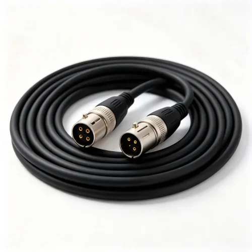
Cable strain relief is the cheapest way to stop field failures, and it is also the detail most B2B cable drawings leave undefined. A connector can be gold-plated, the conductor correctly sized for its ampacity, and the jacket rated for the right temperature — and the assembly will still fail within months if the transition between the rigid connector and the flexible cable is not engineered. This guide explains how strain relief works, the bend radius rules that govern it, and exactly what to specify in your next RFQ.
What Is Cable Strain Relief and Why It Fails
Cable strain relief is any feature that transfers mechanical load away from the electrical termination and onto the cable jacket — or, better, onto the equipment chassis. Without it, every tug, bend, or vibration is absorbed by the solder joint or crimp barrel, which are the weakest points in the assembly.
Three mechanical forces account for almost all field returns:
- Axial pull. An operator yanks the cable to unplug it. The load travels straight into the termination and either fractures the solder fillet or pulls the conductor out of the crimp barrel.
- Bending fatigue. Repeated flexing at the connector exit work-hardens the copper strands. They break one at a time, producing the classic “intermittent connection” symptom that passes a quick continuity check but fails under vibration.
- Torsion and vibration. Twisting during installation, or continuous machine vibration in industrial cabinets, accelerates both of the above.
In practice, most conductor breakage happens within about 25 mm of the connector exit — exactly the zone a properly designed boot or gland is meant to protect.
Bend Radius Rules: Fixed vs. Flexing Installations
Bend radius is measured on the inner surface of the bend and is normally expressed as a multiple of the cable’s overall diameter (OD). Tighten it beyond the limit and you deform the insulation, compress the shield braid, and shift the impedance of data pairs. Never pull a cable into a bend while it is under tension — that is how most installation damage happens.

| Installation type | Typical minimum bend radius | Practical notes |
|---|---|---|
| One-time static install | 4 × OD | Acceptable for wiring that is never moved again |
| Occasional flex / service loop | 6–8 × OD | Test equipment, patching, portable devices |
| Continuous flex (drag chain) | 10–12 × OD | Requires fine-stranded conductor and PUR or TPE jacket |
| Shielded or coaxial | 10 × OD | Tighter bends deform the braid and shift impedance |
| Fibre optic patch | 10–20 × OD (30 mm min.) | Macro-bending loss rises sharply below the limit |
Strain Relief Options Compared
Choosing a retention method is a trade-off between pull-out performance, unit cost, and tooling investment. The table below summarises the options we quote most often for export programmes.
| Method | Pull-out improvement | Best for | Trade-offs |
|---|---|---|---|
| Moulded / overmoulded boot | 3–5× | High-volume USB, DC and audio assemblies | Tooling cost; geometry fixed once tooled |
| Compression cable gland (PG / metric) | 5–10× | Panel-mount and IP67/IP68 enclosures | Needs a panel cut-out and correct clamp range |
| Adhesive-lined heat shrink | 2–3× | Prototypes, repairs, low volume runs | Cosmetic variance; limited flex life |
| Aramid (Kevlar) cord grip | 8–15× | Rugged, defence and aerospace builds | Higher unit cost and manual assembly time |
| Spring / bend protector | 2–4× (bending only) | Handheld devices, stage and studio audio | Adds length and stiffness to the assembly |
How to Specify Cable Strain Relief in an RFQ
A supplier can only quote what you describe. Include these seven items and you will get comparable, buildable quotations instead of optimistic samples:
- Mechanical load. Pull force in newtons, number of mating and flex cycles, minimum bend radius, and load direction.
- Flex class. Static, occasional flex, or continuous flex in a drag chain — this drives conductor stranding and jacket choice.
- Retention method. Overmould, gland, cord grip or a combination.
- Cable OD range and jacket material. The clamp must grip the jacket, not slip over it; PVC, PUR, TPE and LSZH all clamp differently.
- Environment. IP rating, temperature range, and exposure to oil, UV or chemicals.
- Validation data required. Ask for pull-test, flex-test and bend-test reports, not just a sample.
- Termination style. Solder or crimp; a crimp barrel with an integral strain-relief wing performs far better than a bare crimp.
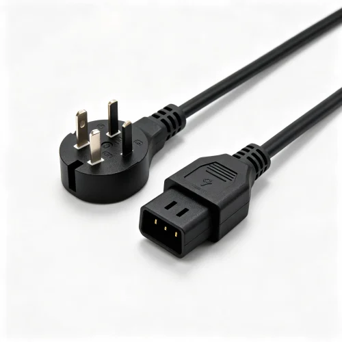
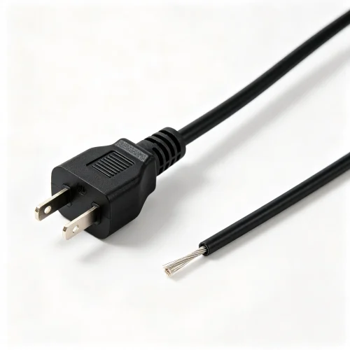
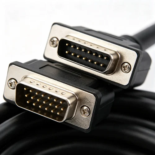
For panel-mounted builds, the gland and the connector must be specified together — see our panel-mount and waterproof connectors range, and match the clamp range to the cable you select from our power cords and power cables or serial and industrial communication cables lines.
Validation Tests Before Mass Production
Strain relief is proven on the bench, not on the drawing. Three tests catch most problems before tooling is locked:
- Pull test. Hold the specified force (typically 50–80 N for signal cables, higher for mains) for 60 seconds. Conductor movement at the termination must stay under about 1 mm.
- Flex test. Cycle the assembly through ±90° or 180° while monitoring continuity. Targets range from 10,000 cycles for occasional flex to several million for drag-chain cable.
- Environmental cycling. Thermal cycling, humidity and salt spray verify that the boot material has not shrunk away from the jacket.
These are the same disciplines covered in our cable assembly testing guide, where hi-pot, continuity and insulation resistance are explained in detail. Strain relief is a mechanical feature, but it is verified with electrical measurement.
The Cost Perspective
Adding a proper moulded boot or gland typically adds 3–8% to unit cost. A single field return, by contrast, costs shipping, replacement and engineering time — and often a customer relationship — commonly 20 to 50 times the price of the strain relief that would have prevented it. For USB cable assemblies and network and fibre cables shipped in volume, that arithmetic is rarely close.
Standards bodies publish baseline terminology and test methods for bend performance; a useful starting reference is bend radius on Wikipedia.
Get a Strain Relief Recommendation for Your Assembly
Send us your drawing, cable OD, pull-force requirement and target flex cycles, and our engineering team will come back with a recommended retention method, tooling estimate and validation plan — usually within one working day.