
Cable testing is the step that separates a shipment which installs cleanly from one that comes back six months later as a warranty claim. For B2B buyers importing wire harnesses, power cords or data assemblies, the four standard electrical tests — continuity, insulation resistance, hi-pot (dielectric withstand) and pull/retention — cost pennies per unit at the factory and thousands of dollars to skip. This guide explains what each test actually detects, the values worth asking for, and how to write them into your next RFQ so they are contractually binding rather than optional.

Why Cable Testing Matters in B2B Procurement
A single mis-wired pin inside a 5,000-piece order can halt a customer’s assembly line, and the recovery cost — air freight, rework, line-down penalties — routinely exceeds the value of the entire order. Electrical testing converts that risk into a predictable, auditable line item.
Testing is also your strongest leverage point during price negotiation. A supplier quoting 8% lower may be skipping 100% hi-pot inspection and relying on batch sampling instead. When you specify the test method, test voltage, dwell time and acceptance limit up front, you remove the ambiguity that makes two quotes impossible to compare.
The Core Cable Testing Methods Compared
Each test targets a different failure mode. They are complementary, not interchangeable — a cable can pass continuity and still fail hi-pot, because a hairline pinhole in the insulation does not interrupt the conductor path.
| Test | What it detects | Typical setting | Common pass criteria |
|---|---|---|---|
| Continuity | Open circuits, mis-wiring, wrong pinout, cold or high-resistance crimps | Low voltage DC, <100 mA | Correct pinout; loop resistance below spec (often <1–5 Ω) |
| Insulation resistance (IR) | Damp or degraded insulation, contamination, thin dielectric, moisture ingress | 250–1000 V DC | >100 MΩ, frequently >500 MΩ at 500 V DC |
| Hi-pot / dielectric withstand | Pinholes, insufficient creepage, conductor-to-shield breakdown | 1.5–3 kV AC for 1–60 s | No breakdown; leakage current below specified mA |
| Pull / retention | Weak crimps, poor strain relief, overmolding voids | Axial load per specification | No conductor displacement or resistance shift |
1. Continuity Testing
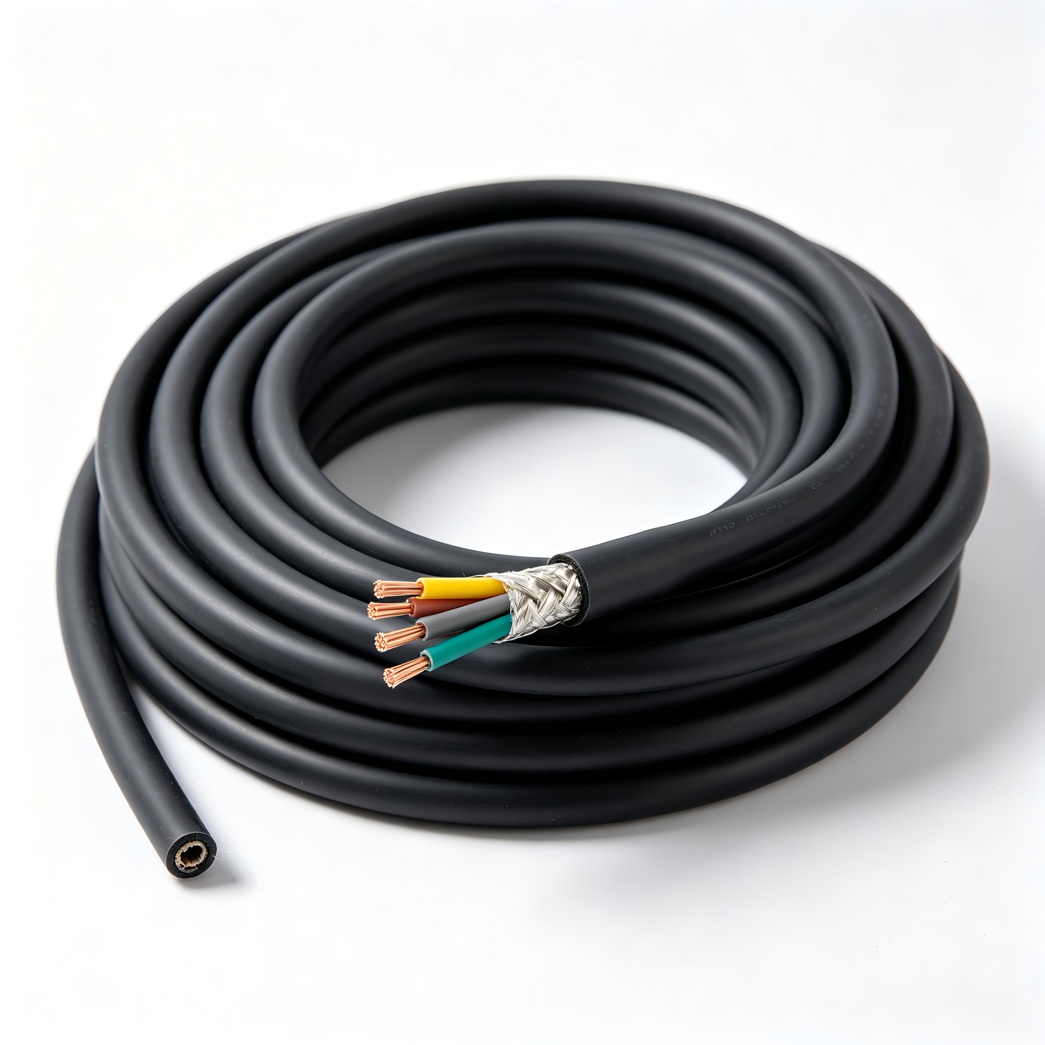
Continuity verification is the foundation. A low-current source is applied between both ends of each conductor while the tester checks that the intended pin maps to the intended pin — and, just as importantly, that no unintended connection exists between adjacent conductors. On multi-core assemblies this “cross-talk” or mis-wire check is where most assembly errors are caught. Always require 100% testing rather than AQL sampling for anything that plugs into a powered device.
2. Insulation Resistance Testing
IR testing applies a DC voltage between the conductor and the shield or between adjacent conductors, then measures the resulting leakage in megaohms. It is a sensitive indicator of insulation quality, moisture absorption and contamination. Because readings drift with temperature and humidity, serious factories condition parts before testing and log the ambient conditions alongside the result.
3. Hi-Pot (Dielectric Withstand) Testing
The hi-pot test stresses the insulation well above its working voltage for a defined dwell time. It is the standard safeguard for mains-connected products and is described in detail as a dielectric withstand test. Specify the test voltage, ramp rate, dwell time and maximum leakage current — a supplier reporting only “hi-pot passed” has given you nothing you can audit.
4. Pull and Mating Cycle Tests
Mechanical tests matter as much as electrical ones. A pull test applies an axial load to the conductor-termination joint to prove the crimp or solder joint survives handling. Mating cycle testing — typically 500 to 1,500 insertions for connectors — predicts field life. Both should be run on samples from each production lot, not only during first-article approval.
Recommended Test Values by Cable Type
Requirements differ sharply between a low-voltage data lead and a mains power cord. The table below is a practical starting point for discussions with your supplier; final values must always follow the applicable product standard.
| Cable family | Continuity | Insulation resistance | Hi-pot |
|---|---|---|---|
| AC power cords | 100% pinout + polarity | >100 MΩ @ 500 V DC | 2–3 kV AC, 1–60 s |
| USB and data cables | 100% pinout + shield | >100 MΩ @ 250–500 V DC | 500 V–1.5 kV AC, 1 s |
| Industrial serial / RS485 | 100% pinout + drain wire | >500 MΩ @ 500 V DC | 1.5–2 kV AC, 60 s |
| Network and fiber patch | Channel / insertion loss | n/a for fiber | Per channel standard |
Cable Testing Checklist for Your Next RFQ
Copy this list into your enquiry so testing scope is quoted, not assumed:
- Test coverage: state 100% electrical testing vs AQL sampling, per test type.
- Test voltage and dwell: exact values for IR and hi-pot, not “per standard”.
- Acceptance limits: maximum loop resistance, minimum IR, maximum leakage current.
- Mechanical verification: pull force per conductor gauge and mating cycle count.
- Equipment and calibration: tester model and last calibration date.
- Documentation: per-lot test report, first-article report, and serial-level traceability for safety-critical parts.
- Environmental conditioning: temperature and humidity at which readings were taken.
Failure Modes That Testing Catches Early
In practice, the defects that reach a factory test bench are remarkably consistent: reversed pinout on custom overmolds, whiskers of stranded copper bridging two adjacent contacts, incomplete crimps that pass a visual check but fail under load, and insulation scored during stripping that only breaks down under hi-pot stress. Every one of these is inexpensive to fix at the source and expensive to find after installation.
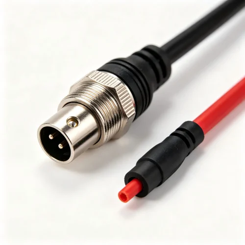
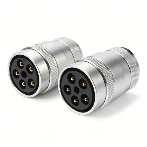
Connectorised assemblies add another variable. Mating interfaces, especially sealed ones such as panel-mount waterproof connectors, should be verified after the sealing gasket and overmold are fitted, because assembly steps downstream of the electrical test can reintroduce faults.
Work With a Factory That Tests Every Unit
At SYY Cable we run 100% continuity and hi-pot inspection on production assemblies, keep calibrated test records per lot, and share first-article reports before mass production begins. If you are comparing quotes or want a second opinion on a testing specification, send us your drawing and target standard.
Request a quote and test specification review — our engineering team replies within one business day.





















One Response